

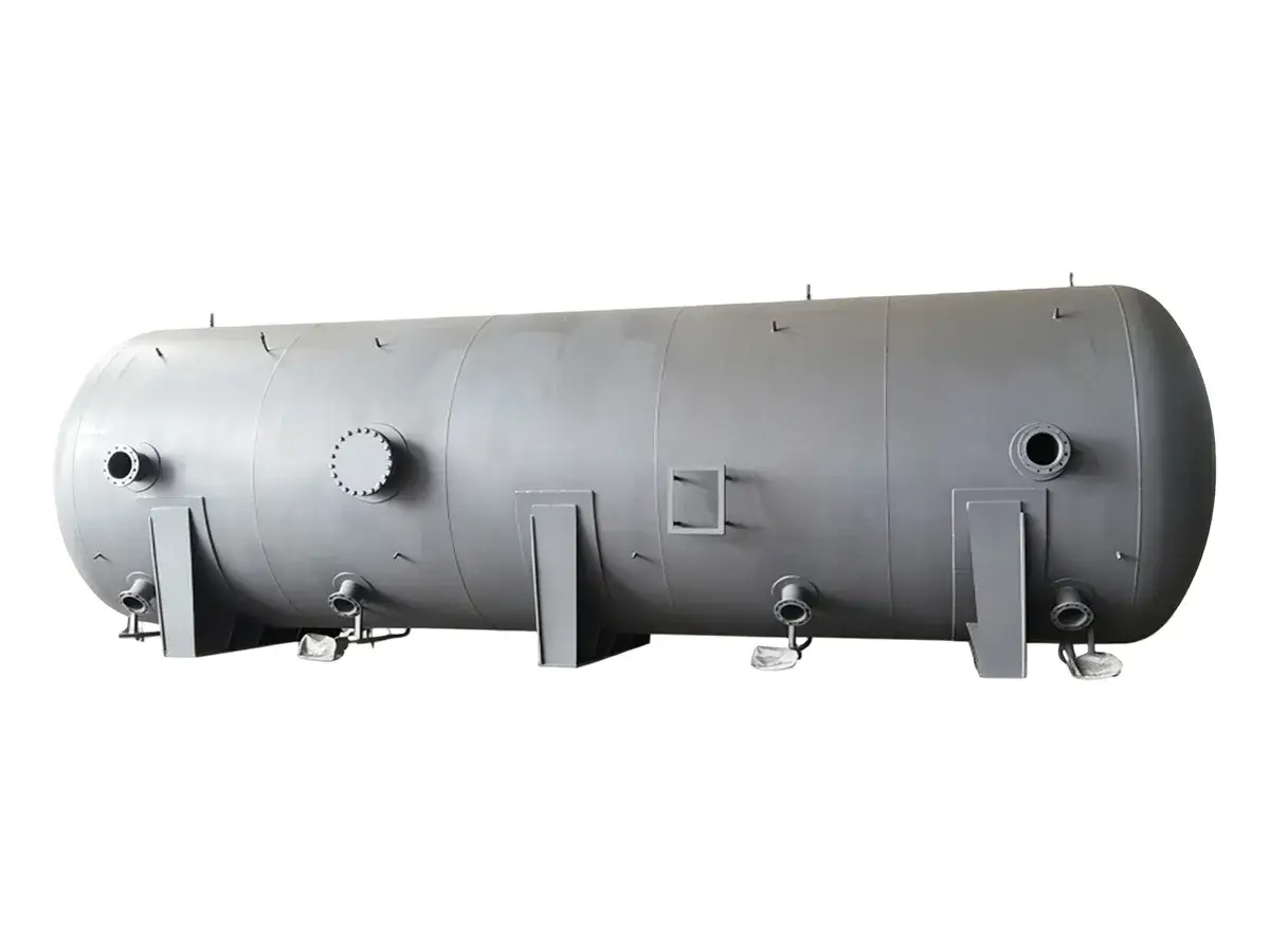
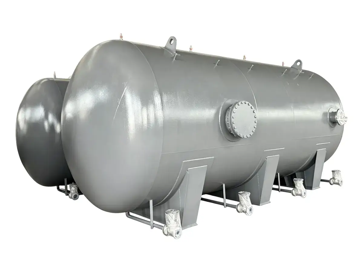
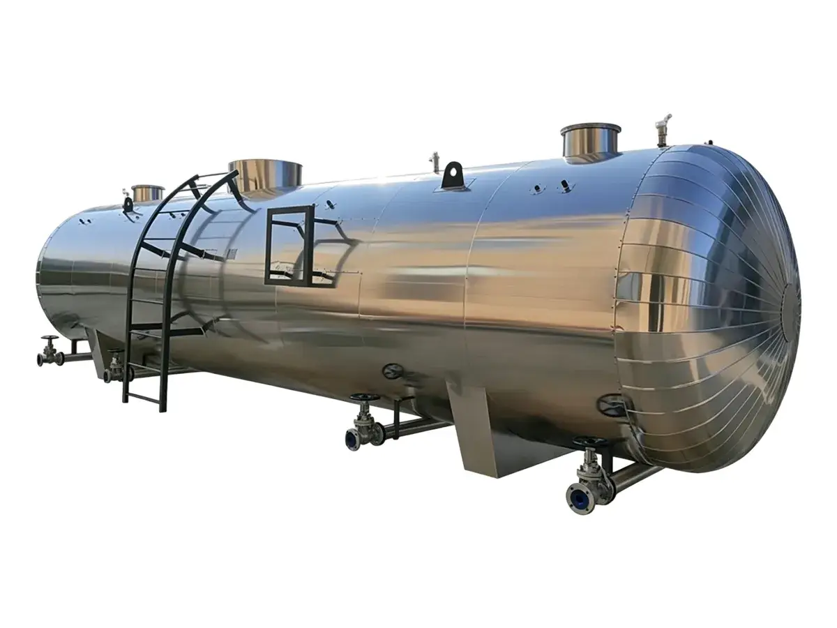
Thermal Energy Storage Tank (Chilled Water TES Tank)
The thermal energy storage tanks store thermal energy in the form of chilled water. The system produces and stores chilled water during off-peak hours, then releases the stored cooling capacity during peak demand periods. By shifting cooling production away from peak operating hours, the thermal storage tank helps balance chiller system loads and improves overall energy management. The tank uses the natural density difference between chilled water and warmer return water to create thermal stratification. Cold water remains at the bottom of the tank, while warmer water stays at the upper section. A stable thermocline layer separates the two temperature zones and maintains effective storage performance.
During off-peak periods, chilled water produced by the chiller system is stored inside the TES tank. When cooling demand increases, chilled water is discharged from the bottom of the tank and supplied to the facility. At the same time, warmer return water enters from the top of the tank. The density difference between the two water temperatures creates natural stratification with minimal mixing between the cold and warm water layers. To maintain a clear thermocline layer, we apply an advanced diffuser design in the inlet and outlet piping. The diffuser controls water velocity and flow distribution to maintain smooth fluid movement inside the tank and reduce turbulence.
- High-Pressure and Large-Capacity Design: Pressure rating up to 25 bar with storage capacity from 100 litres to 15,000 litres.
- Stainless Steel Construction: Tank materials include austenitic stainless steel 304, 316, 316L, and 316Ti.
- Advanced Welding Technology: High-quality flux-cored wire welding and plasma arc welding technologies are applied for reliable tank fabrication.
- Certified Manufacturing Standards: Designed and manufactured according to BS PD5500 and ISO 3834 standards.
- Optimized Diffuser Design: The customized diffuser structure distributes inlet and outlet water evenly, reduces turbulence, and maintains stable thermal stratification between the warm upper layer and chilled lower layer.
- Controlled Internal Water Flow: The internal flow design reduces unwanted mixing between hot and cold-water zones.
- Temperature Monitoring System: Temperature sensors can be installed at different heights of the tank for operating condition monitoring and data collection.
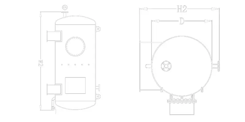
 Vertical Thermal Energy Storage Tank
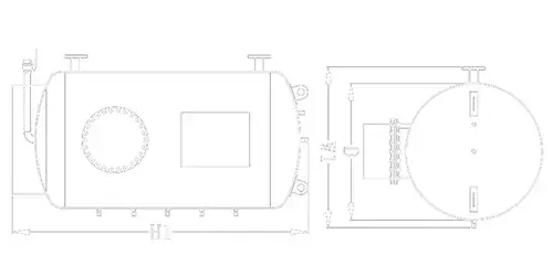
 Horizontal Thermal Energy Storage Tank
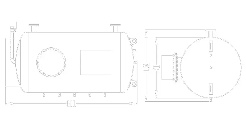
| Model | Capacity | Diameter | Width | Height | Weight | Connection Size | ||||
| D | W₁ | W₂ | H₁ | H₂ | 10Bar | 16Bar | Water inlet | Water outlet | ||
| L | mm | mm | mm | kg | mm | |||||
| 1000 | 900 | 900 | 1820 | 1935 | 1240 | 345 | 430 | 65 | 65 | |
| 1500 | 1000 | 1000 | 2170 | 2290 | 1340 | 430 | 520 | 65 | 65 | |
| 2000 | 1100 | 1100 | 2380 | 2500 | 1440 | 590 | 680 | 65 | 65 | |
| 2500 | 1300 | 1300 | 2190 | 2310 | 1640 | 680 | 830 | 65 | 65 | |
| 3000 | 1300 | 1300 | 2560 | 2680 | 1640 | 780 | 1020 | 65 | 65 | |
| 4000 | 1300 | 1300 | 3320 | 3440 | 1640 | 1000 | 1350 | 80 | 80 | |
| 5000 | 1500 | 1500 | 3160 | 3280 | 1840 | 1250 | 1650 | 80 | 80 | |
| 6000 | 1600 | 1600 | 3330 | 3450 | 1940 | 1620 | 2180 | 100 | 100 | |
| 7000 | 1600 | 1600 | 3820 | 3940 | 1940 | 1950 | 2460 | 125 | 125 | |
| 8000 | 1800 | 1800 | 3510 | 3630 | 2140 | 2120 | 2680 | 125 | 125 | |
| 9000 | 1800 | 1800 | 3910 | 4030 | 2140 | 2210 | 2950 | 125 | 125 | |
| 10000 | 2000 | 2000 | 3580 | 3700 | 2340 | 2280 | 3230 | 125 | 125 | |
Remarks
- Horizontal
- Vertical
- The dimensions shown in the above tables are standard factory specifications. Other specifications can be customized according to customer requirements.